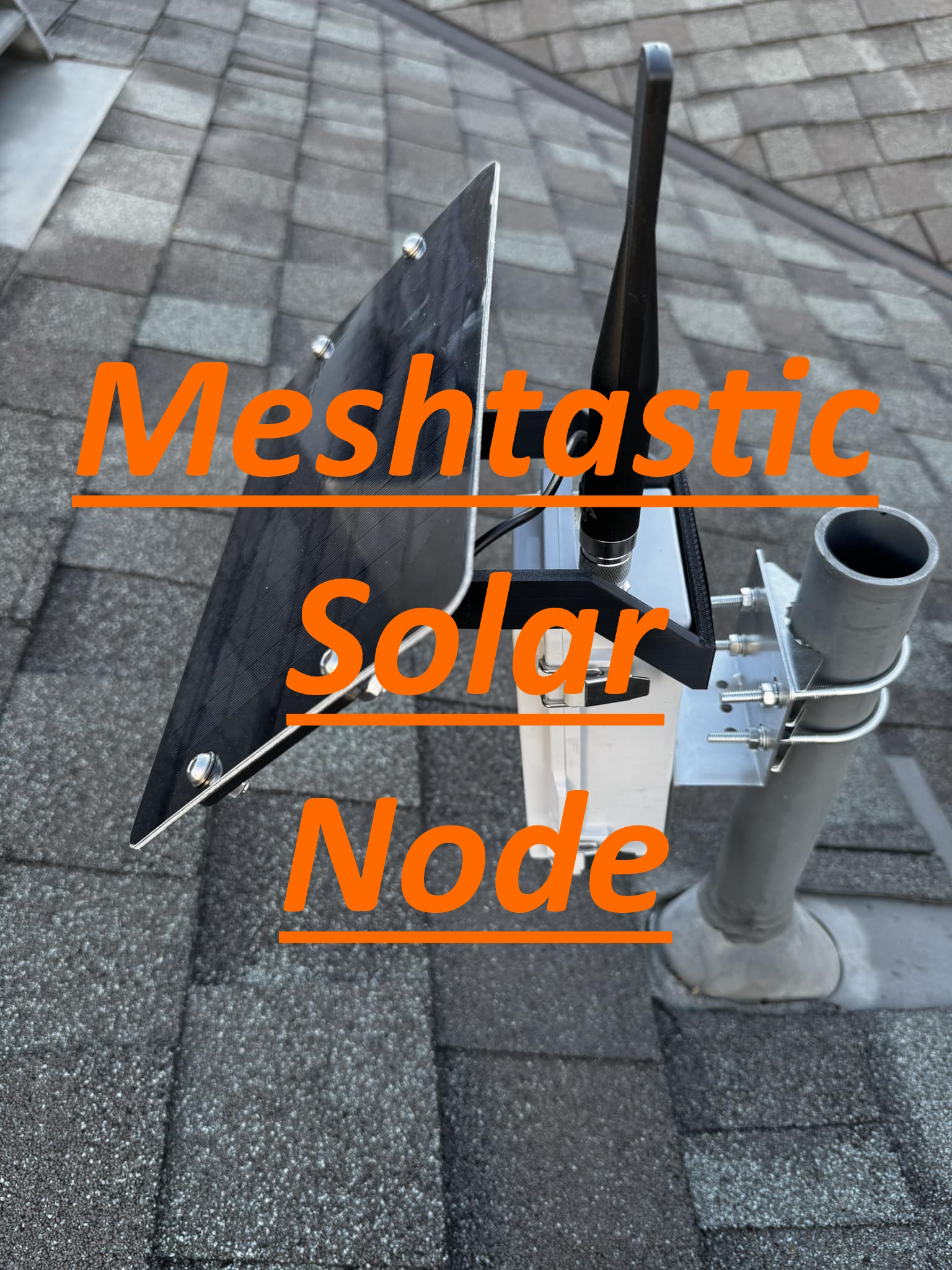
Mesh Solar Node
Parts
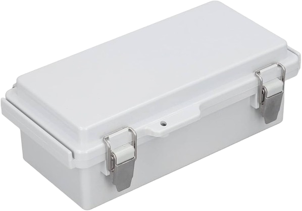
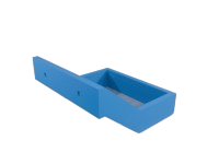
Waterproof Enclosure
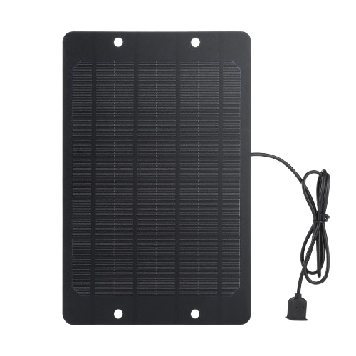
Solar Panel
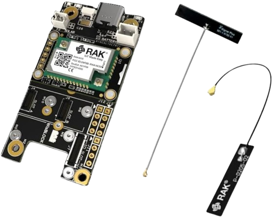
Rak 4630
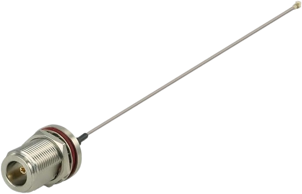
N type Female to IPEX

Alfa 915 Antenna
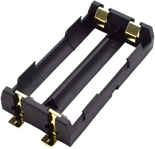
x2 18650 Battery Holder
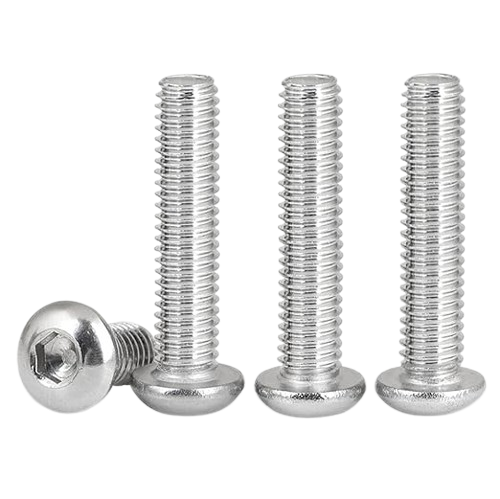
x5 40mm M6 Screws
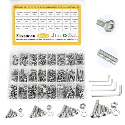
Assorted Screw Set
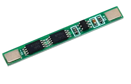
5 Amp BMS
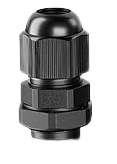
PG7 Cable Gland
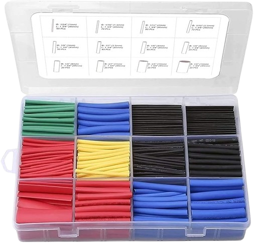
Heat Shrink Tubing
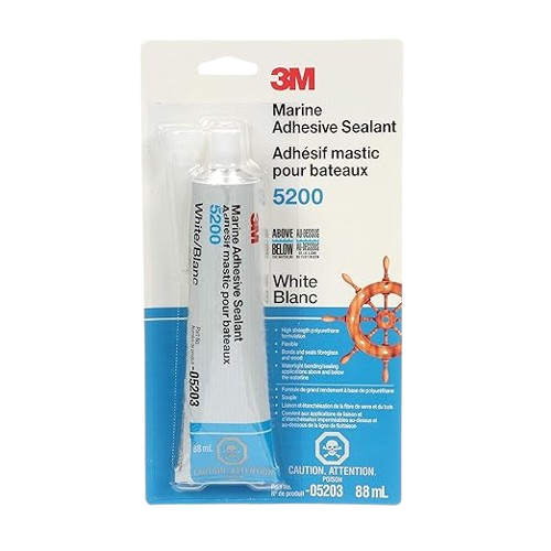
Marine Adhesive
Battery Power Cable
Solar/BMS Power Cable
Solar Power Cable

Right Solar Panel Bracket
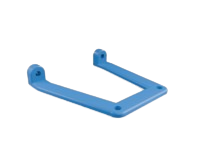
Left Solar Panel Bracket

Side Bracket (need too print 2)

Pivot Bracket
Solar Panel Mount Bracket
Optional Parts
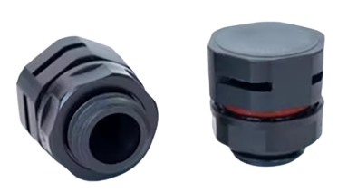
Breather Vent
Build
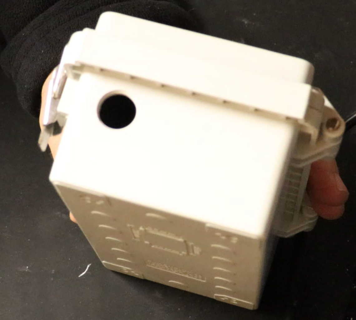
1.
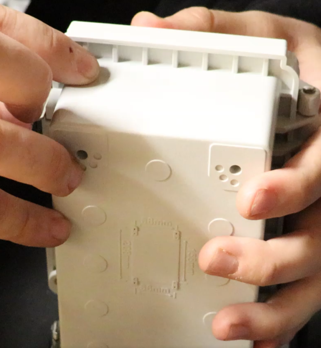
From the second notch, measure to the center 3/8"
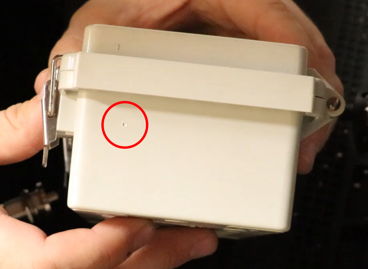
Circled is where the notch should be marked.
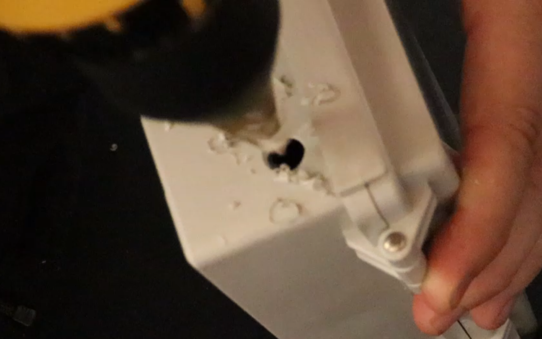
2.
Here we drilled out a 5/8" hole.
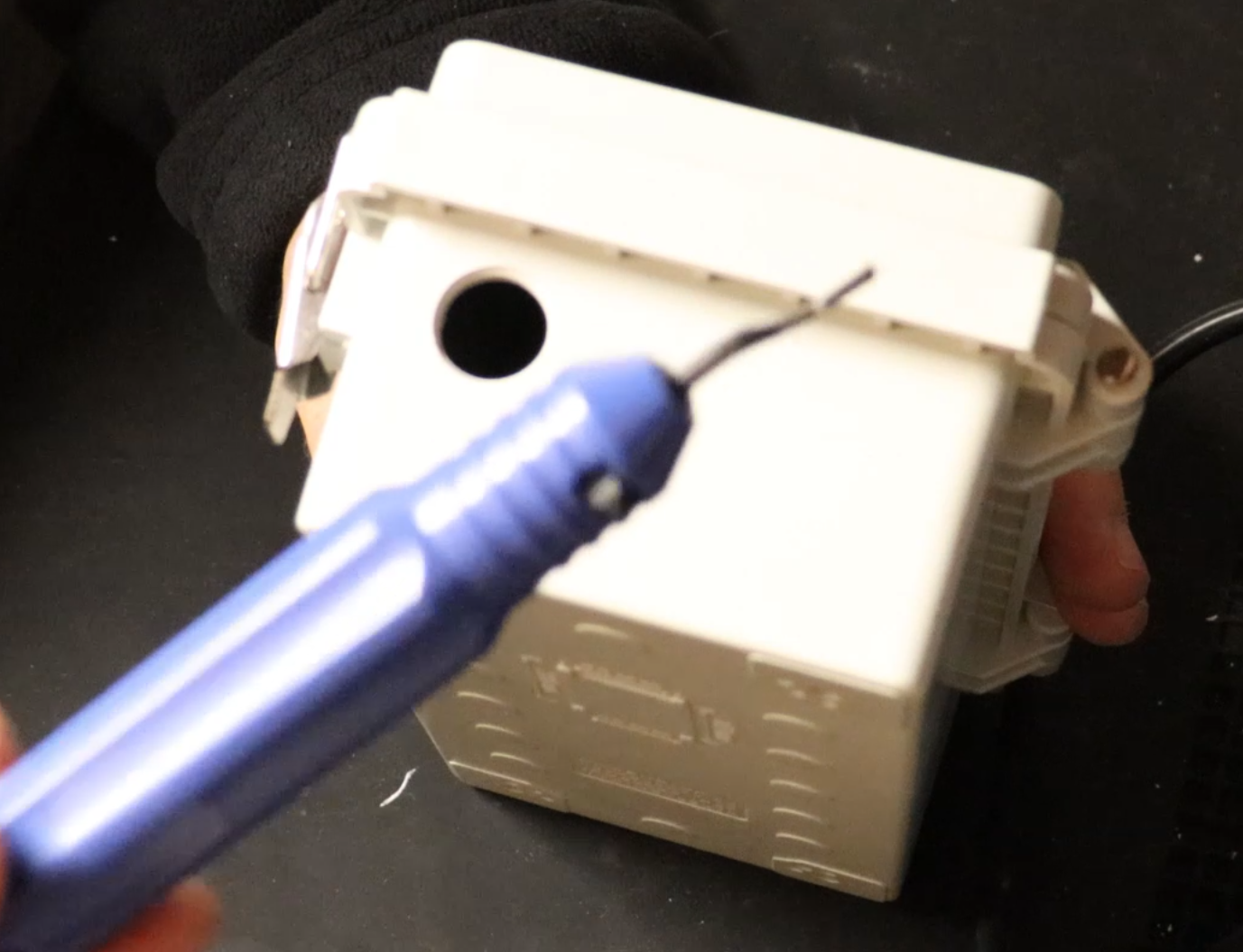
The hole will be a little small too small for the N-type Female connector to fit through. So here we make the hole just a little bigger using a deburring tool.
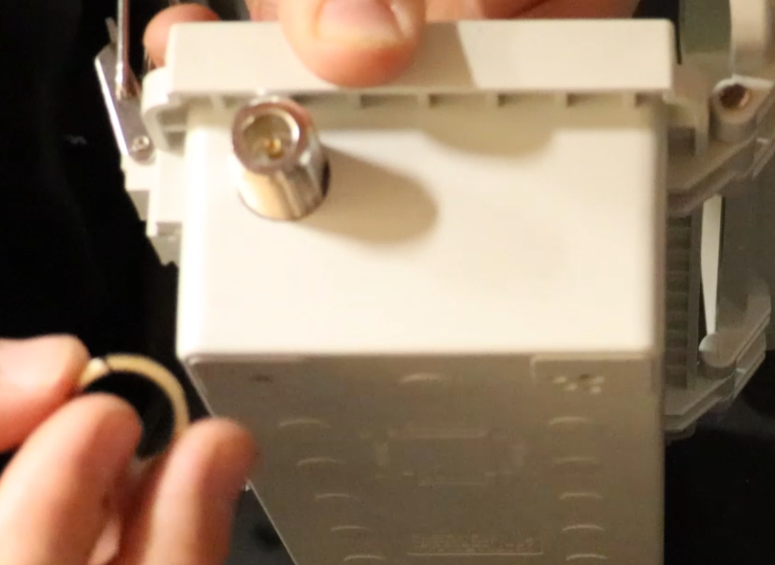
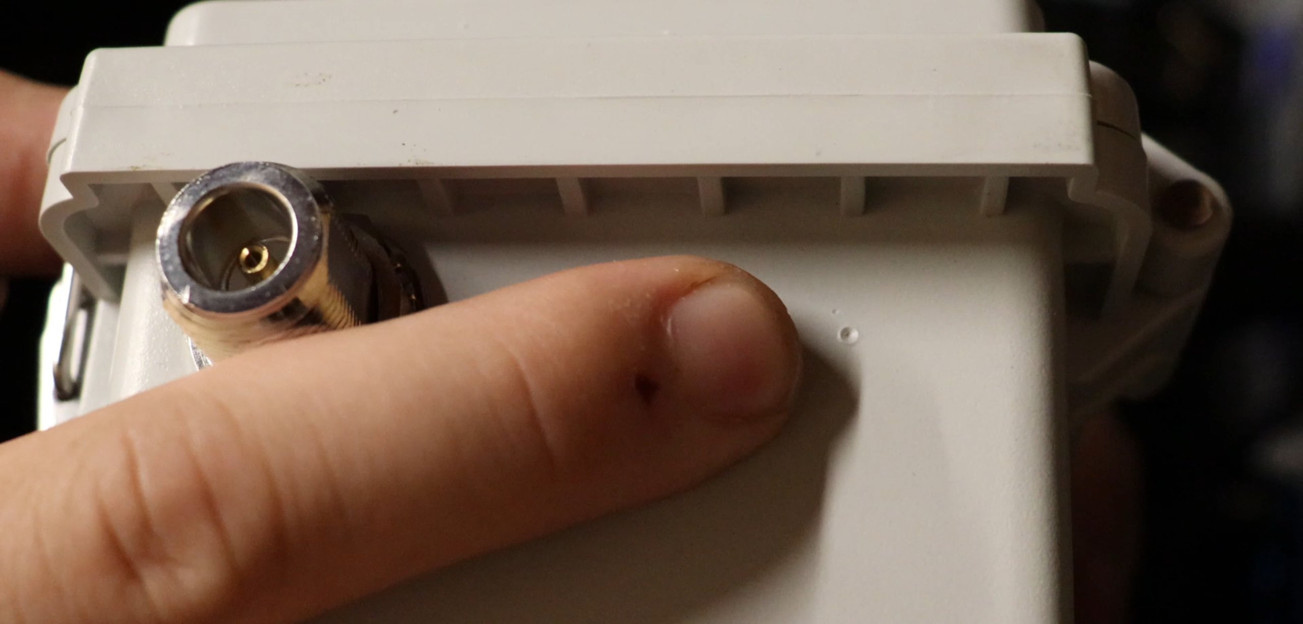
Once the hole is just big enough, insert the N-typpe Female Connector and tighten it down.
3.
Now make the same 3/8" measurement on the other side and mark the box. This is where the cable gland will go.
Drill out a 7/16" hole.
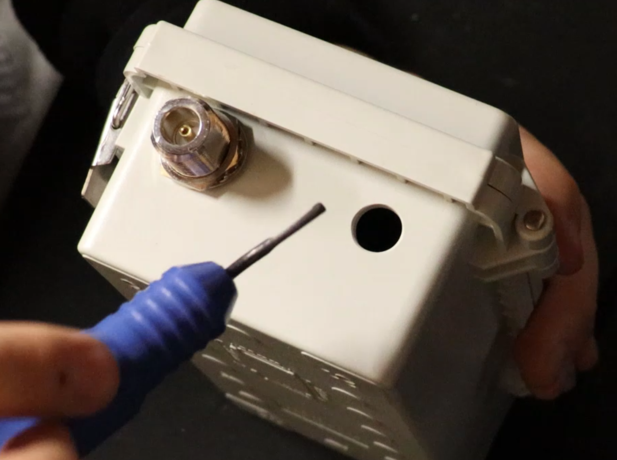
Again, the hole will be a little small, so we use the deburring tool again.
4.
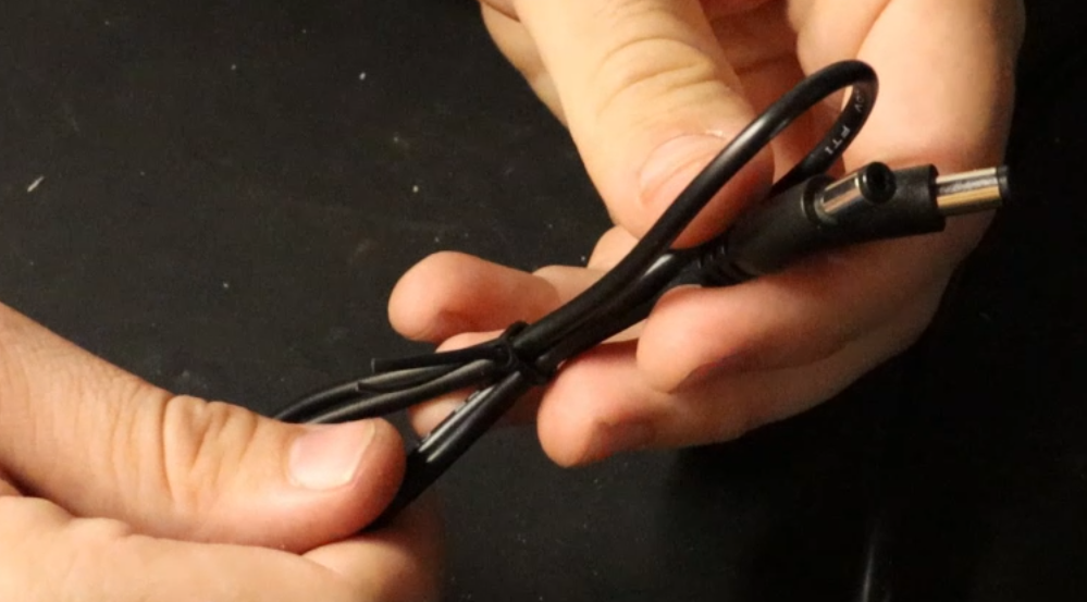
This is the power cable that comes with the SoShine 6Watt Solar Panel.
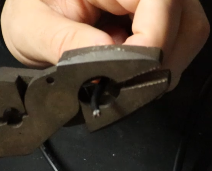
Snip one of the ends off and strip about 1 1/2" of the cable.
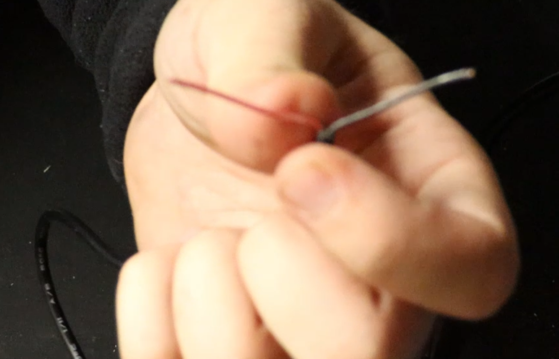
After stripping off 1 1/2" there will be a red and black wire. You will want to also strip these. (not too much though).
5.
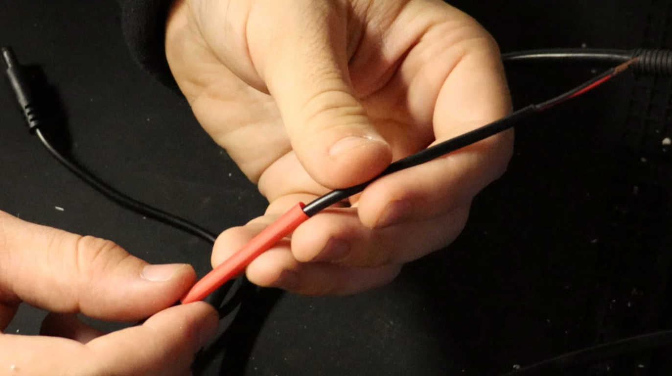
Here we will be tripple layering heat shrink tubing.
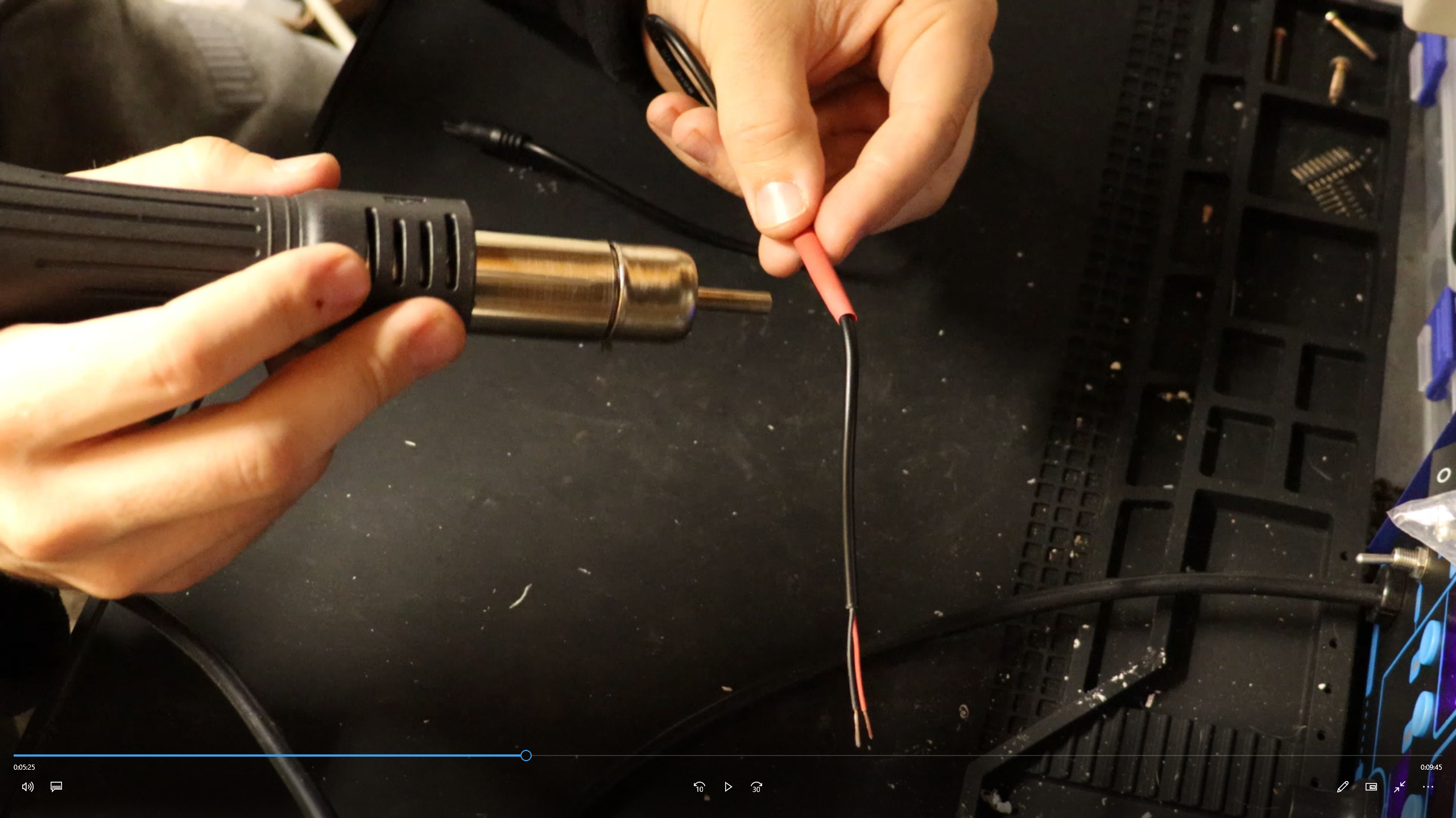
Shrinking the tubing.
6.
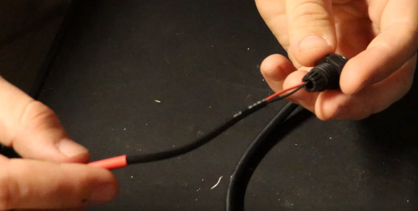
Now insert the cable through the cable gland until the heat shrink tubing part is enclosed.
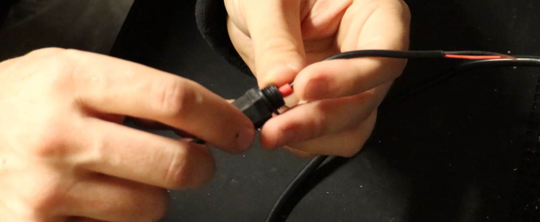
Tighten down the cable gland all the way.
7.
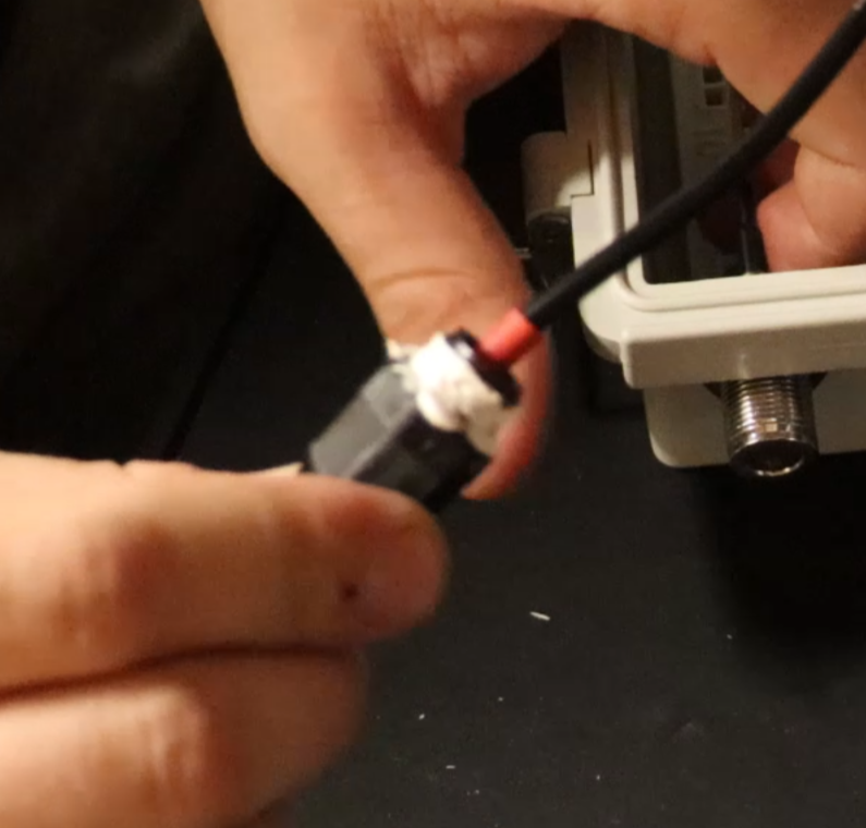
Cover the threaded end of the cable gland with Marine Adhesive.
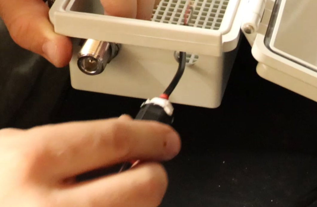
Insert the stripped wire ends with the cable gland into the waterproof enclosure.
8.
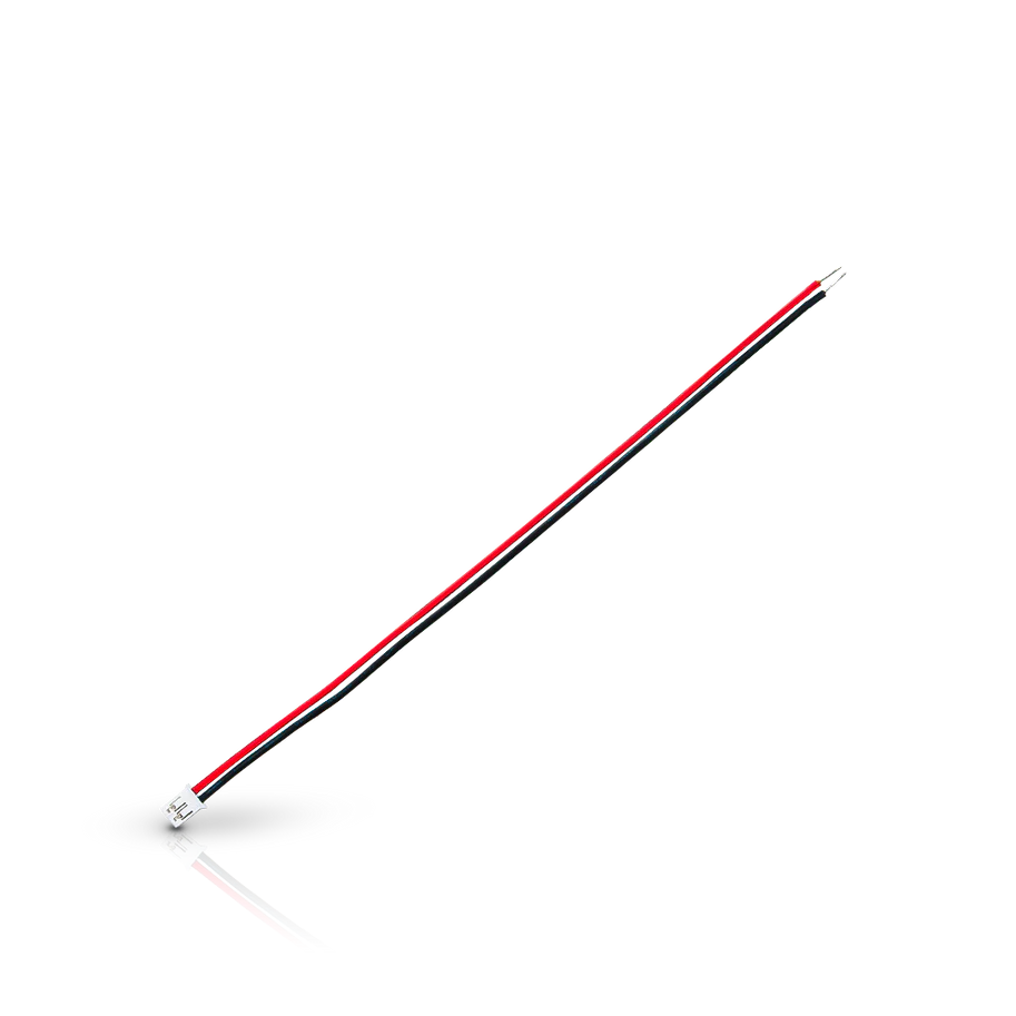
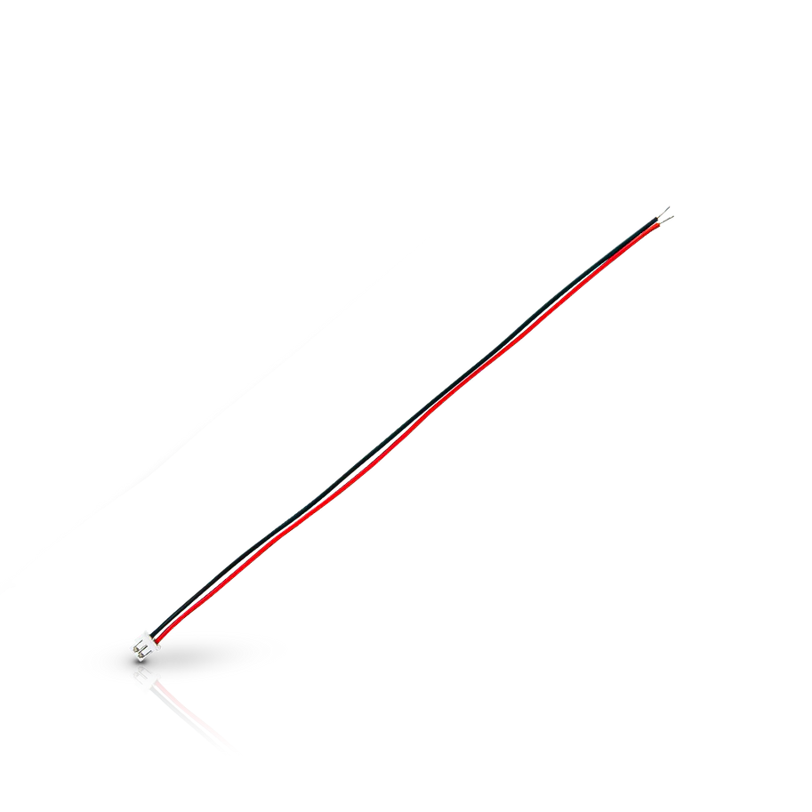
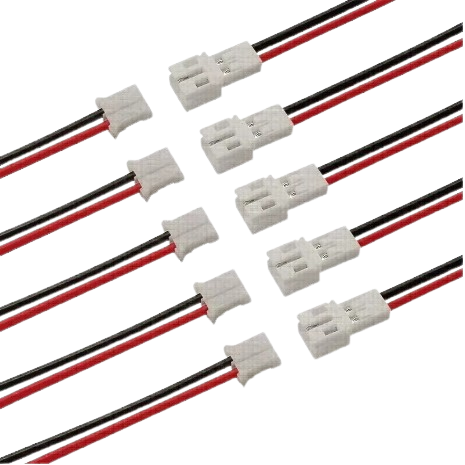
These are the Solar Power Cables from the parts list. (It will be 1 male and 1 female connector).
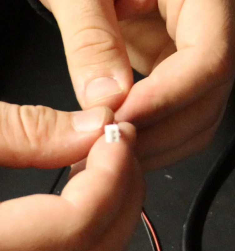
This is the Battery connector cable.
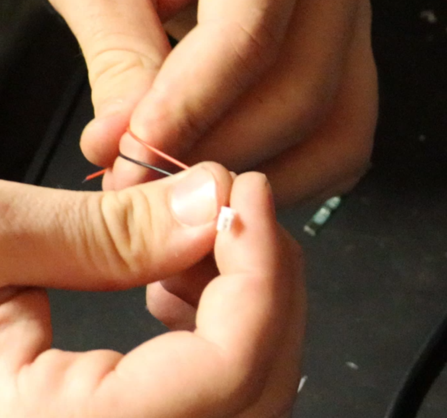
This is the Solar/BMS Power Cable connector.
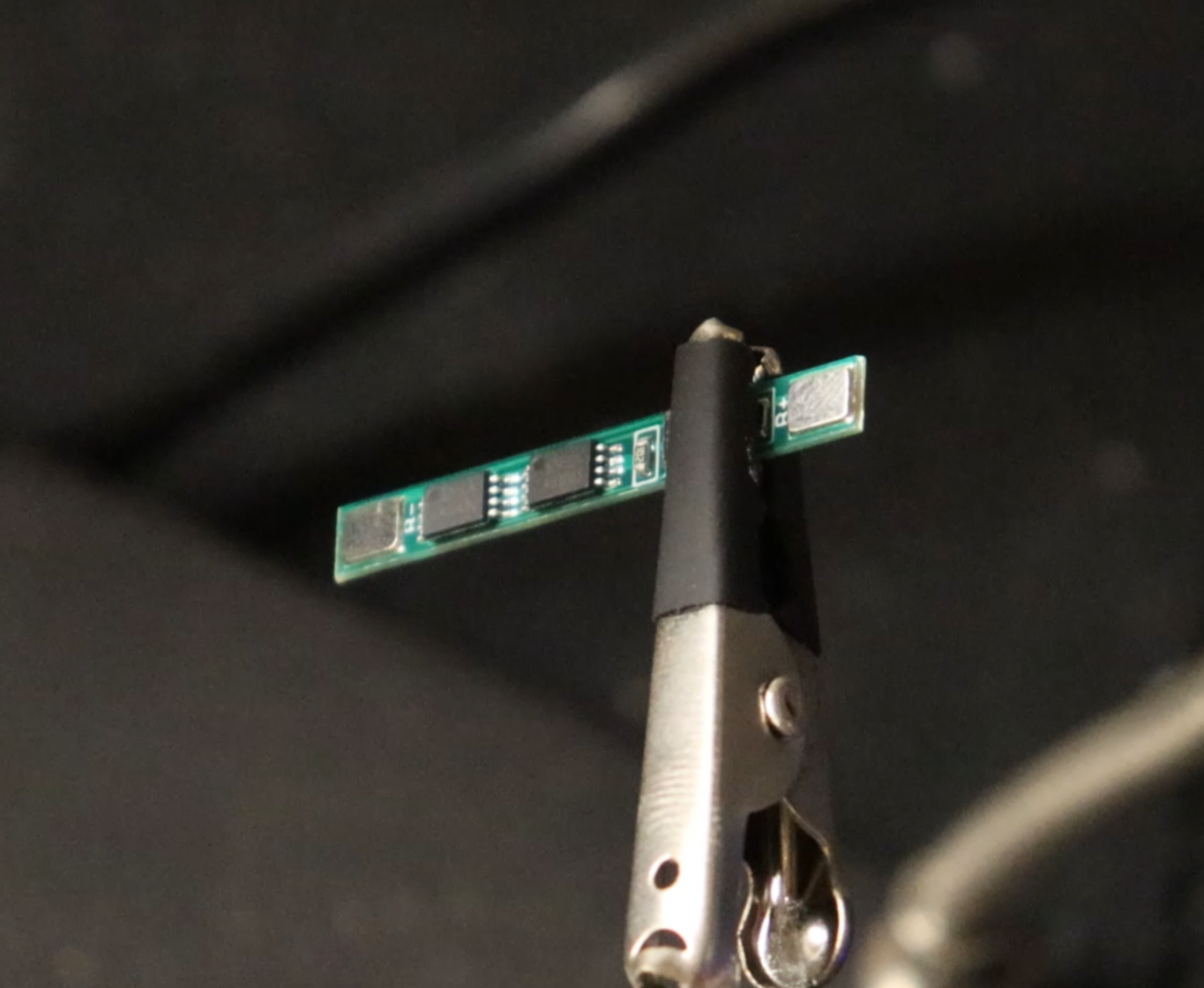
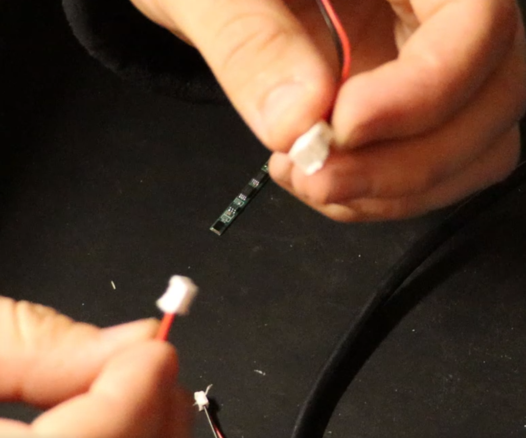
This is the 5amp BMS
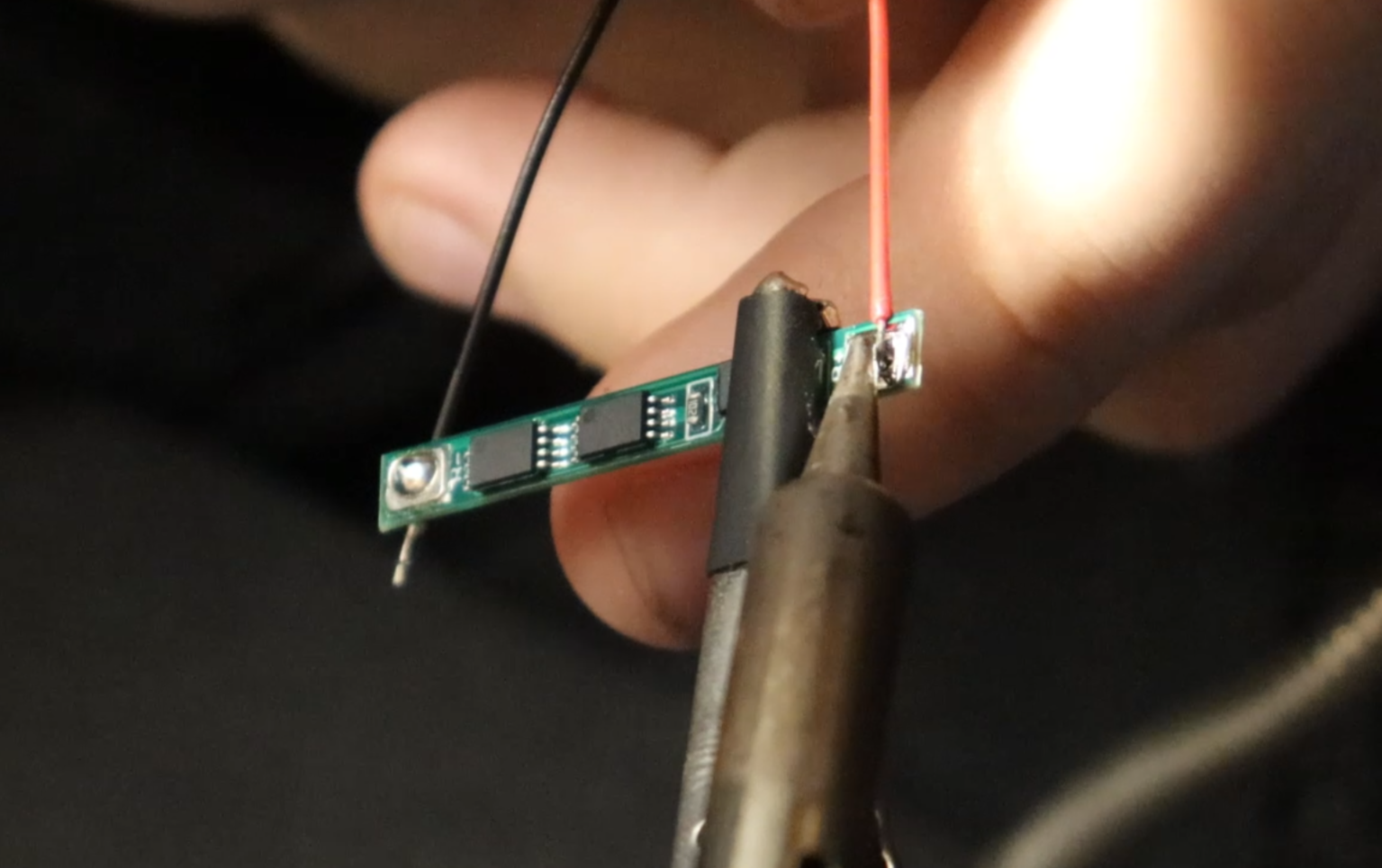
Now solder a Male Solar/BMS Power Cable to the outer pads of the BMS and the Solar Power Cable to the inner pads of the BMS.
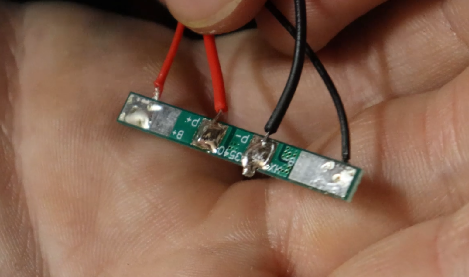
This is the BMS all soldered up.
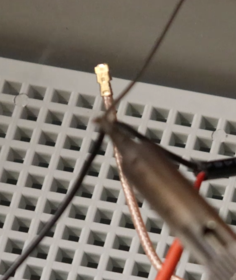
Now solder a Female Solar/BMS Power Cable to the power cable that we delt with in step 4. (SLIDE HEAT SHRINK TUBING ON BOTH LEADS BEFORE SOLDERING)
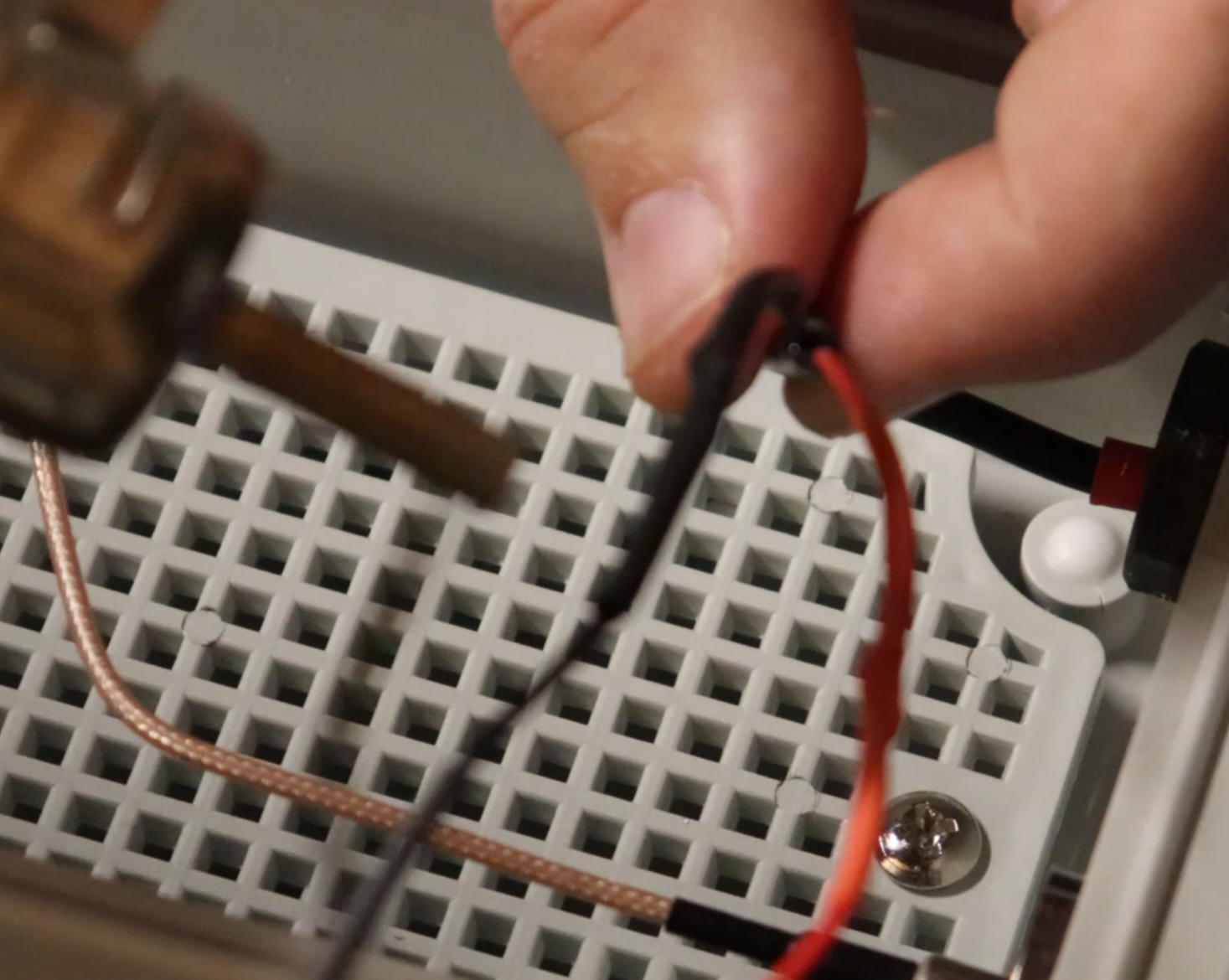
Slide the heat shrink tubing over the soldered area and shrink it.
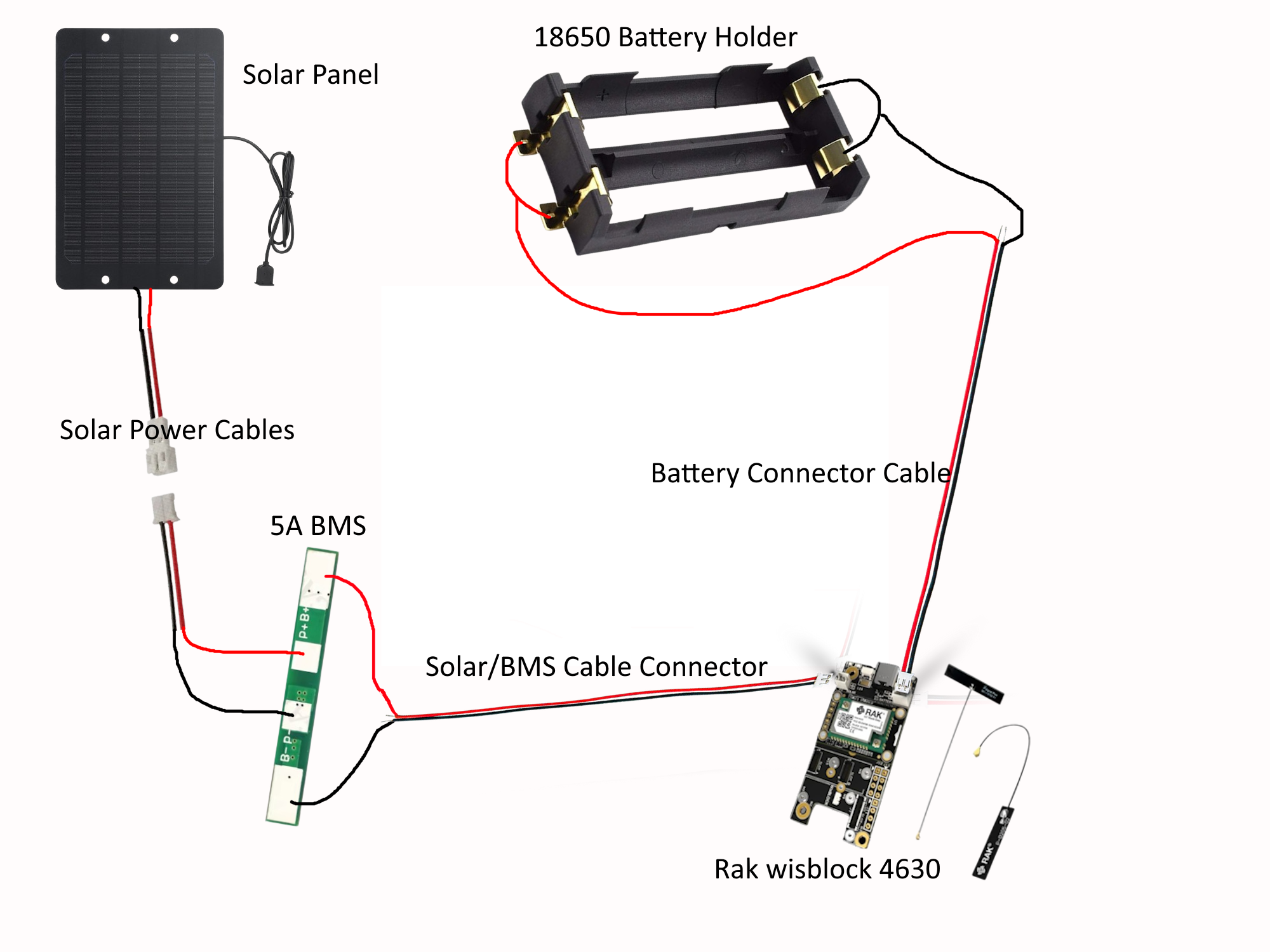
This is a diagram I made to go off of.
9.
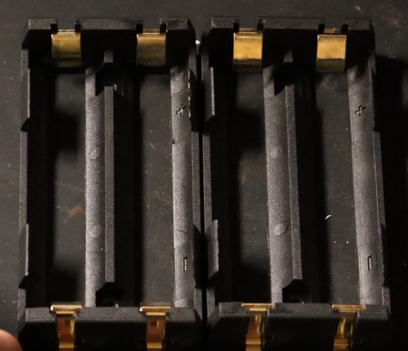
Here are the 18650 Battery Holders.
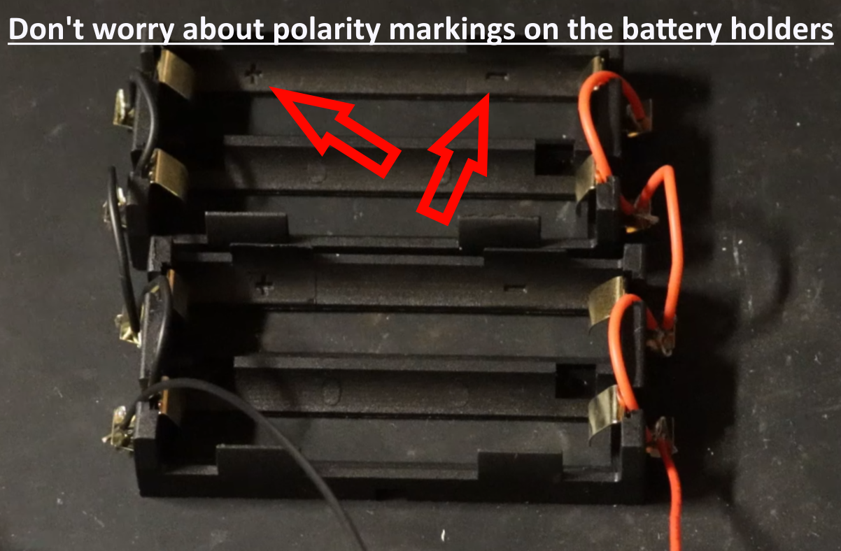
Wire the 18650 battery holders in Parallel.
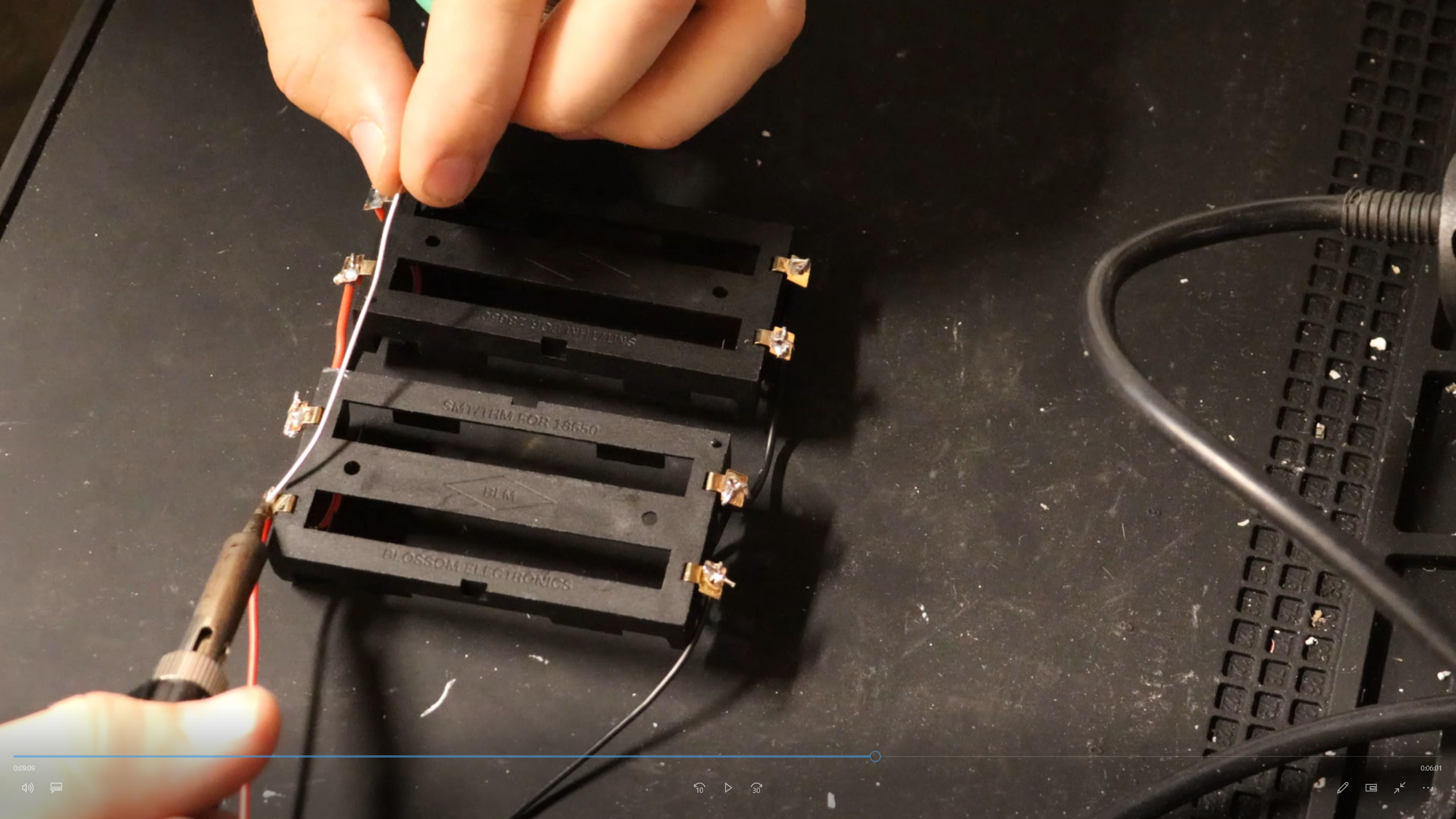
Solder the wired battery holders together.
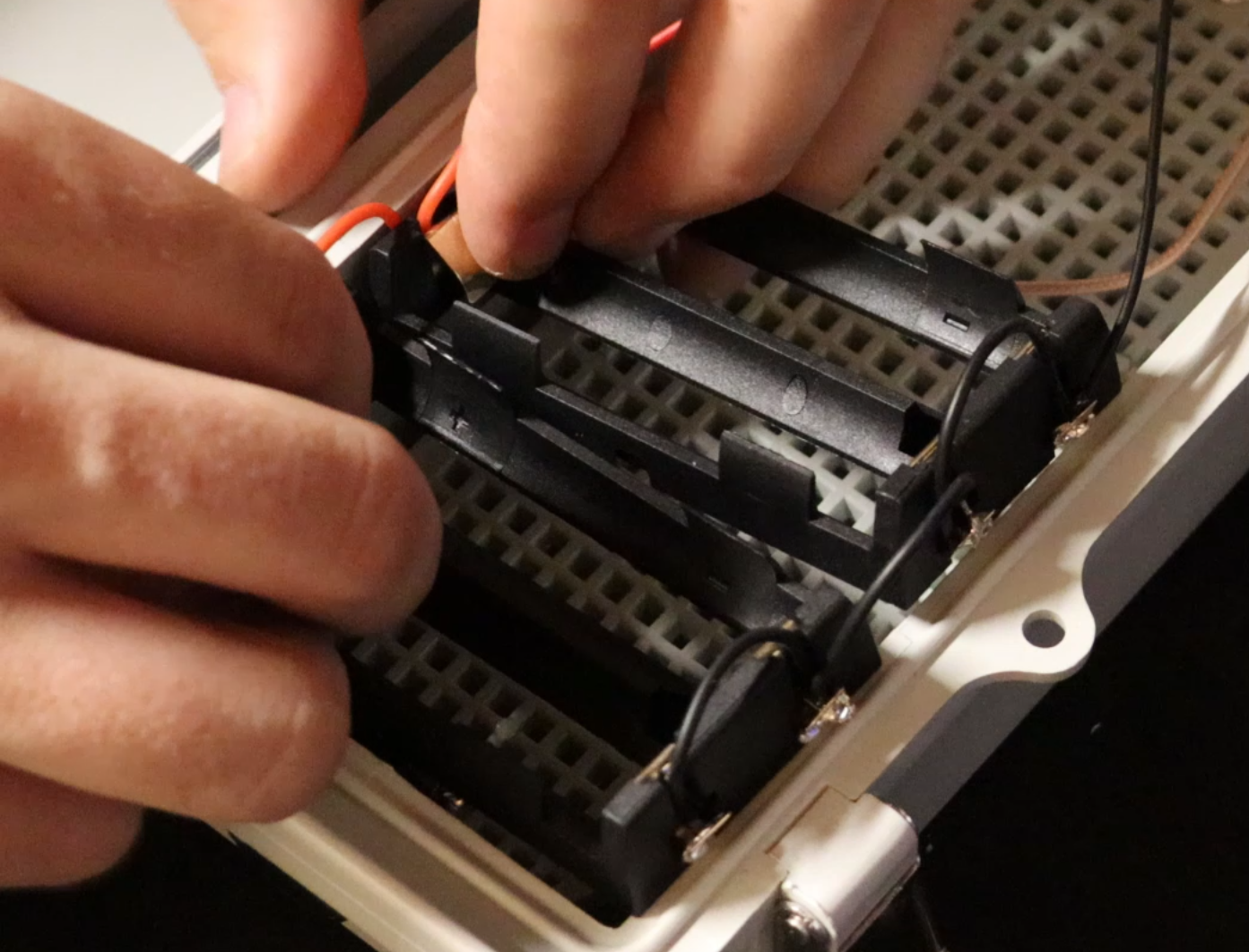
Fit the newly created battery pack into the waterproof housing.
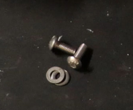
10.
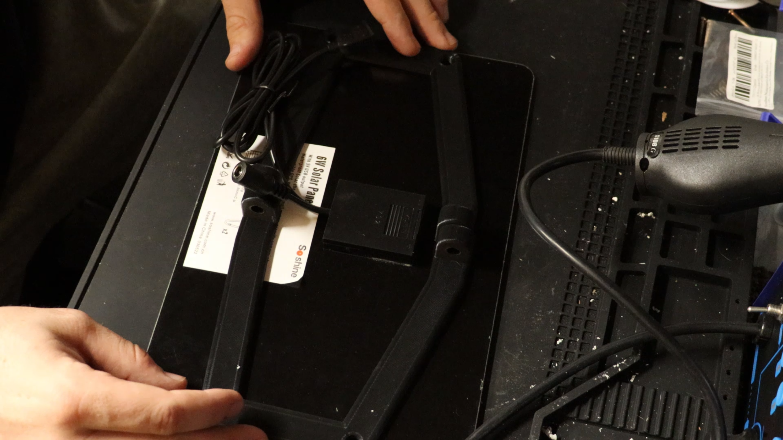
Take the right and left Solar Panel brackets and fit them to the solar panel.
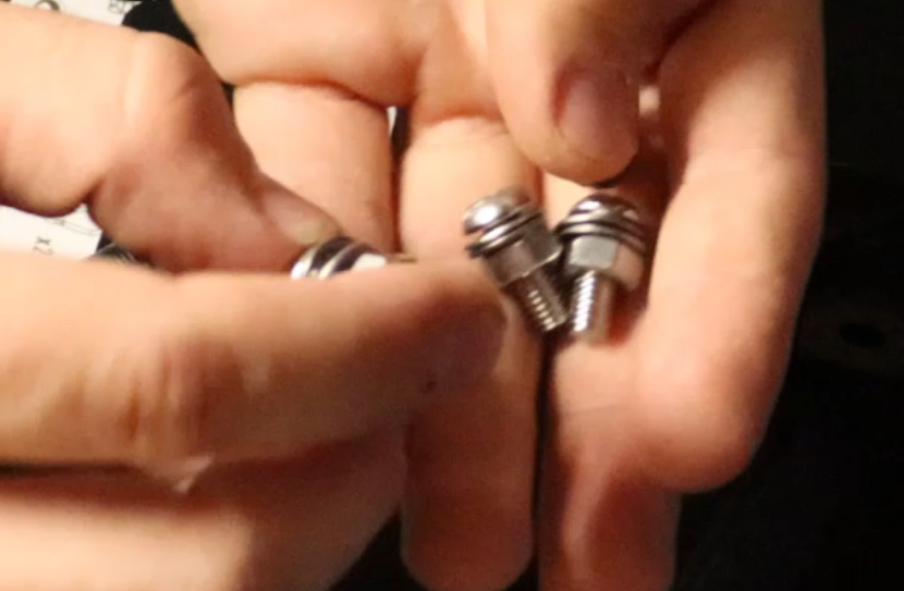
Here I use x4 16mm M6 screws with 2 washers and 1 nut each.
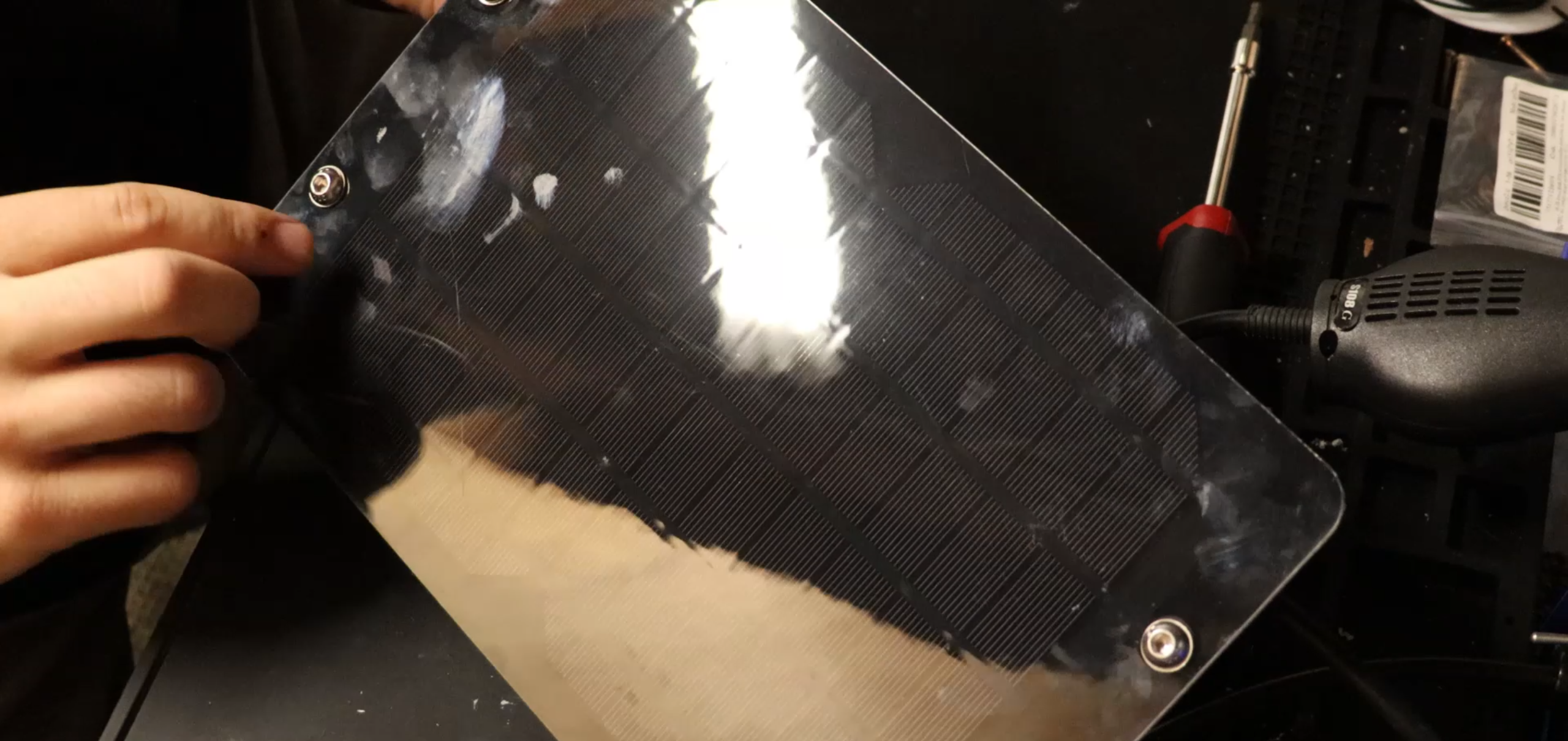
This is what the Solar Panel should look like with the screws.
11.
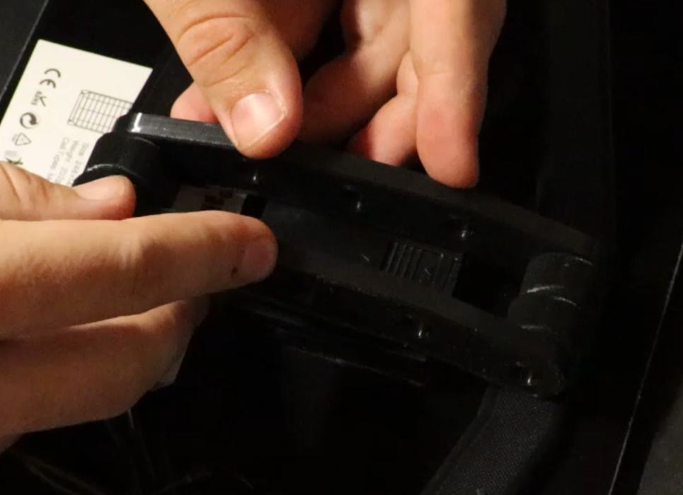
Take x2 Side Brackets along with the Pivot Bracket and fit them to the back of the Right and Left Solar Panel brackets.
This is the Pivot Bracket.
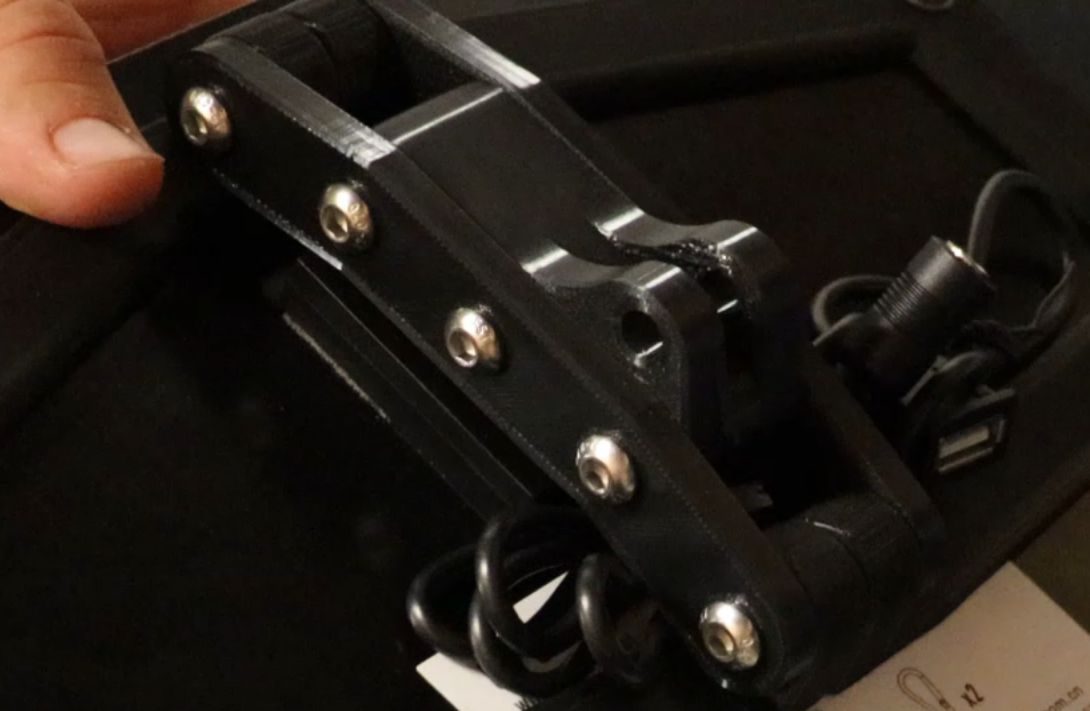
Use x5 40mm M6 screws and 5 nuts. 1 nut for each screw.
12.
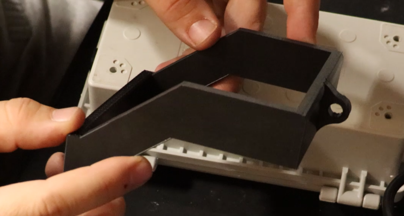
This is the Solar Panel Box Mount Bracket
These are 12mm M5 screws with 2 washers.
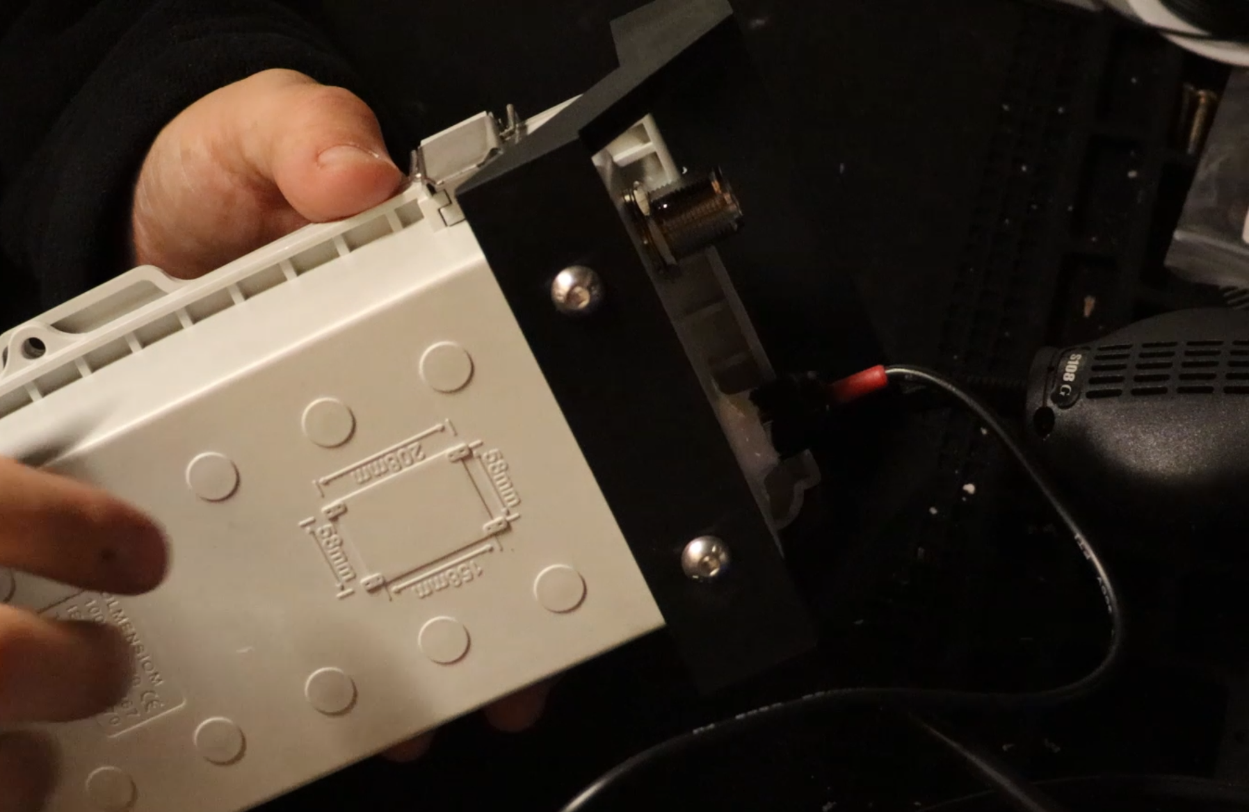
Fix the Solar Panel Box Mount Bracket to the top of the waterproof enclosure using the 12mm M55 screws.
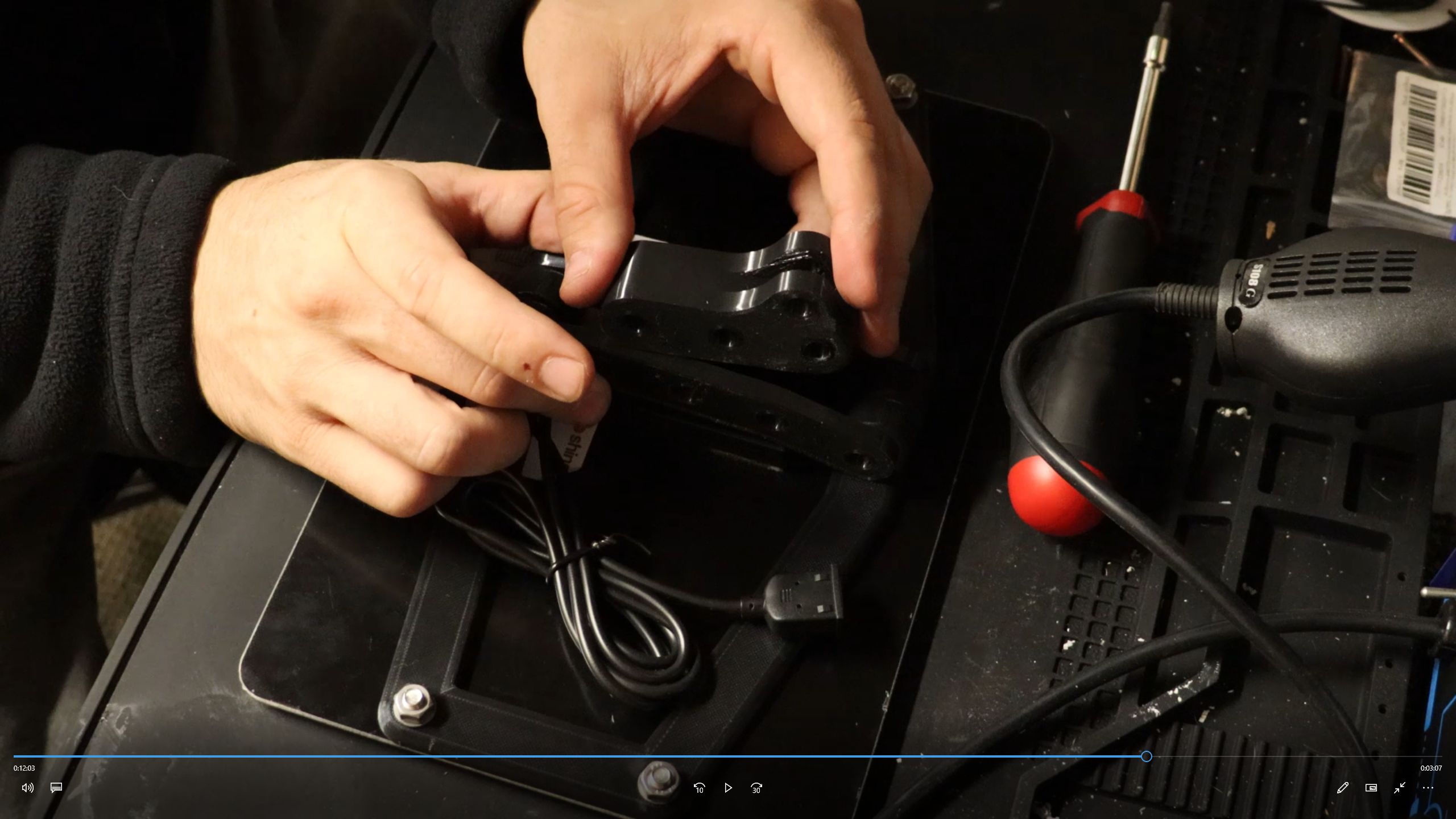
13.
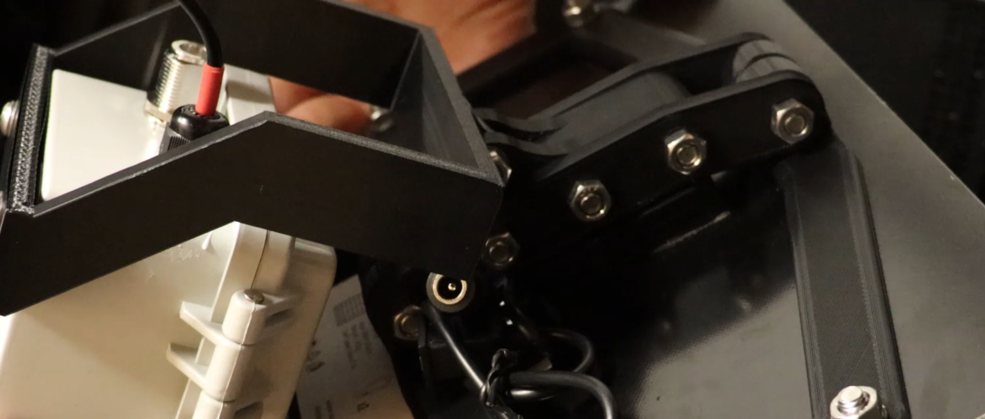
Now attach the pivot points of both the Pivot Bracket and the Solar Panel Box Mount Bracket using 1 30mm M6 Screw with 2 washers and 1 nut.
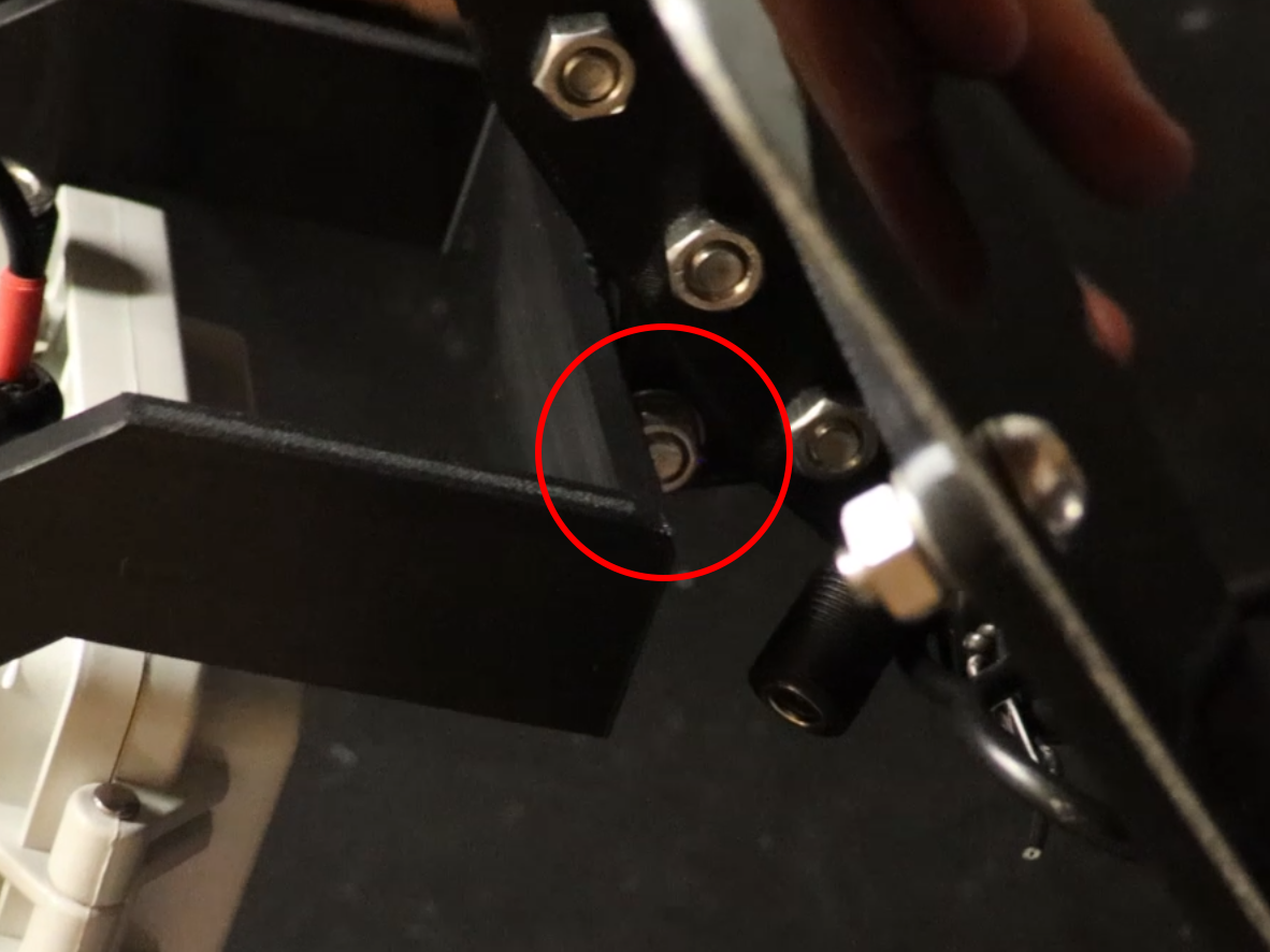
This is just another angle of where to attach the pivot bracket.
14.
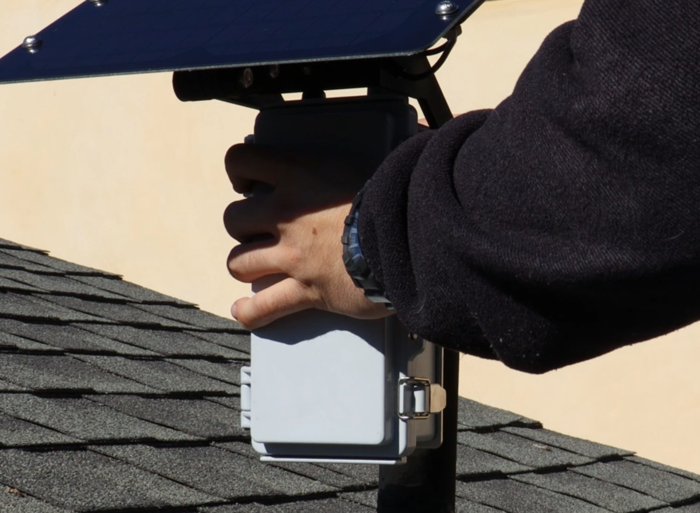
Add some mounting hardware and mount your newly made Mesh Solar Node.
15.
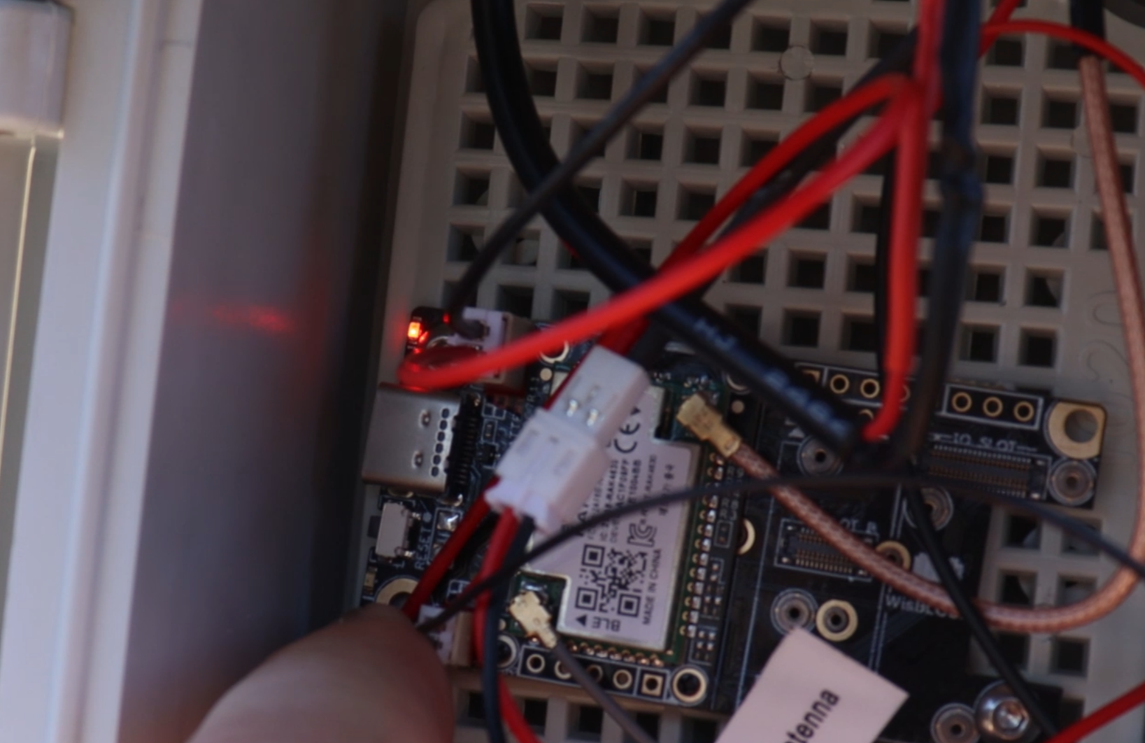
When plugging everything in, you will see two lights. This Solid bright red light indicates that there is power coming in from solar.
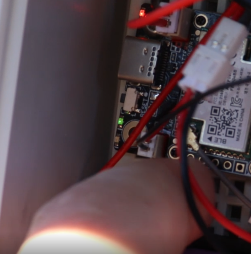
This Blinking green light indicates that the unit is on and running.